Angiogenesis Quantification Lübeck (AQuaL)
System requirements:
The Java SE
Runtime Environment, available for free download at the homepage of
Sun Microsystems, is required to run AQuaL.
Sun Microsystems offers the Java SE Development Kit (JDK) for free, which is required to compile the source code again after modification.
AQuaL startup and image selection
AQuaL can be started by double-clicking the AQuaL.jar file or by a batch file that contains the following line:
java -Xmx400m -jar AQuaL.jar
"-Xmx400m" sets the amount of RAM Java can use to 400MB. If you encounter any problems running AQuaL these may rely on the small amount of
RAM that Java can allocate if you have started AQuaL by double-clicking the AQuaL.jar file.
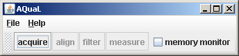
The user interface is displayed after
AQuaL is started. Disabled buttons are only accessible after
selecting images using the File
menu. Furthermore, the acquire
button is only displayed if JMF is installed on the computer.
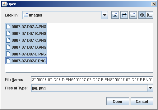
Images are selected in the file chooser upon clicking Open Image/Images in the File menu.
In case of selecting only a single image filter and measure buttons are enabled in the user-interface. Image alignment is only accessible if multiple images have been selected.
Image alignment
Choosing align displays a file browser (upper left) that holds the names of the selected images. After selecting two overlapping images they are displayed in frames (source: upper right; target: bottom right). A structure that is identical in both images has to be defined by mouse clicks in both pictures. Successful selection of these points is indicated by checkboxes (upper left image at bottom: value accepted) in the file browser. If more than 2 images have to be aligned the next image has to be selected. This third image is displayed in the „target image“ frame and the previous target image is displayed in the „source image“ frame. This makes it necessary to order the images so that the first image overlaps with the second and the second with the third and so forth. The optimal procedure is therefore to name the images accordingly (i.e. image1, image2, etc). At the end of defining the translations by choosing an identical structure in all overlapping images generate composite image calculates the aligned image that is visualized in the „aligned image“ frame (bottom left). Additionally this aligned image is saved prefixed with „aligned“ in that folder which contained the previously selected images.
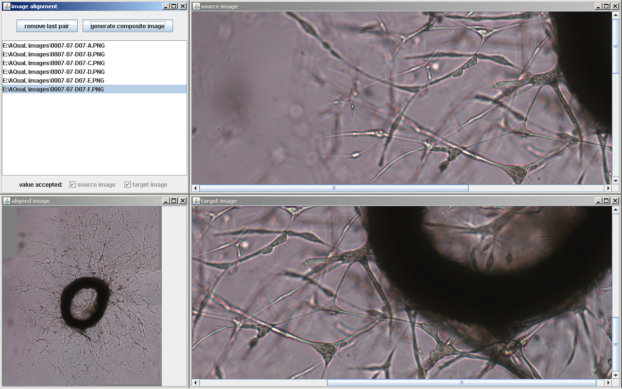
Image filtering
Image filtering and area measurement requires prior calibriation that has to be performed by applying the calibrate system menu. Pixels units can be correlated to any distances measurement.
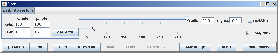
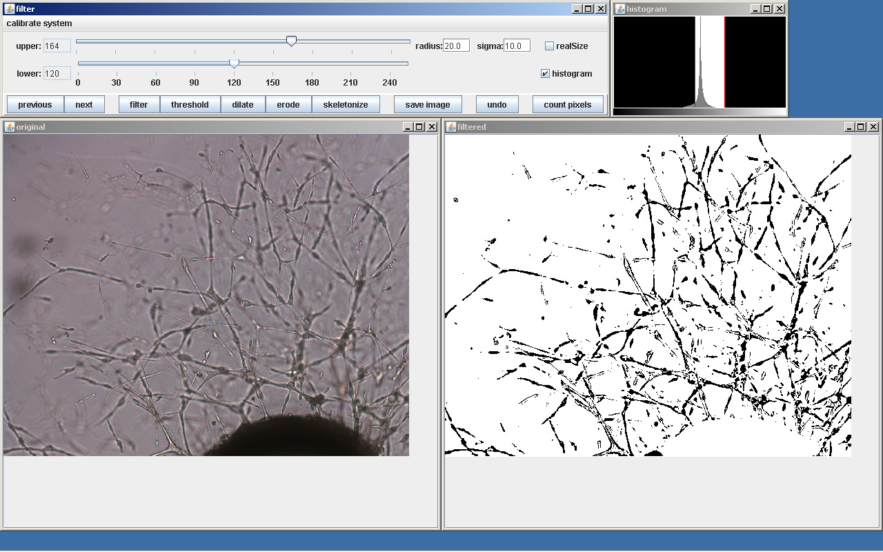
Image filtering involves a procedure that changes pixel values depending on adjacent pixels. The radius determines the number of adjacent pixels that are considered and sigma (standard deviation) their relevance. The higher sigma the higher is the relevance of adjacent pixels. The optimal settings can be best tried by applying different values. The default option is a good starting point. Filtering is executed only after clicking by depending on the radius and sigma settings by clicking filter. After filtering a threshold operation is applied executed after clicking threshold. The upper and lower threshold values can be changed by moving the sliders which is visualized immediately. The optimal selection of the thresholds is supported by displaying the histogram of gray values (upper right frame). The histogram depicts the frequency (or amount) of pixels which exhibit certain gray values. Left values are black or darker and bright pixels are on the right part. The middle peak is the most common color (gray), i.e. the background. This peak should be excluded by sliding to appropriate values. The cutoff of the threshold function is visible in the histogram and pixels in the black area turn black whereas pixels that are shown in the histogram against white will turn white after thresholding. The original image is shown in the left frame and the processed image in the right frame. Images are displayed to fit in the frames, however, activation of the checkbox real size displays them in original size. The processed image can be saved any time by clicking save image. save image resets internal data stores and thus count pixels has to be performed before saving an image. Black pixels and the according area is measured and saved in a textfile by clicking count pixels. This textfile is saved in the folder of which the images were selected.
A
few additional functions are supplied:
1: Dilate
changes pixels to black depending on the surroundings. It can be used
to generate more continuous lines or structures.
2: Erode
depicts only the edge or border of the structure. All pixels within
the structure are turned white.
3: Skeletonize
reduces the structure to its center line (i.e. its skeleton).
Length measurement
Measurement obtaining the length and number of branches requires prior selection of a single image. Furthermore, prior calibriation to correlate pixel units to distance measurement has to be performed by applying the calibrate system menu as explained above.
This program requires point selection using the left mouse button and prior definition of the point type by pressing number keys. The keys that need to be pressed for point type definition and the actual selected point type are displayed in the small frame (left hand). The selected image is diplayed in its original size in the main frame.
Measurements are initiated by defining a starting point (displayed in image in red) by clicking the left mouse button at the required position in the image to mark a starting point. Further measurement points are inserted by mouse clicks and are defined as middle points (displayed in yellow in the image). An end point of the structure is defined by initially pressing the key „2“ and thereafter left-clicking the mouse at the appropriate position. End points are displayed in green in the image. Branches are inserted after pressing „3“. The following mouse click onto a middle point (yellow boxes) in the image changes the selected point into a branching point which is also visualised by a change in color (blue boxes). After defining a branch point, point type switches automatically to middle point. If a tree is completely marked and defined by points and lines the user clicks the right button of the mouse. This initiates the the overall length calculation of the tree which is displayed in a text field to the right. Further informations which are displayed in the text field is the unique number of the tree and the number of branches. The content of the text field is saved in a text file (ASCII) upon clicking save values. The file appears in the folder of the selected image. The size of the diplayed boxes can be adjusted in the options menu. The image including the marked trees can be saved in the same folder by clicking save image.
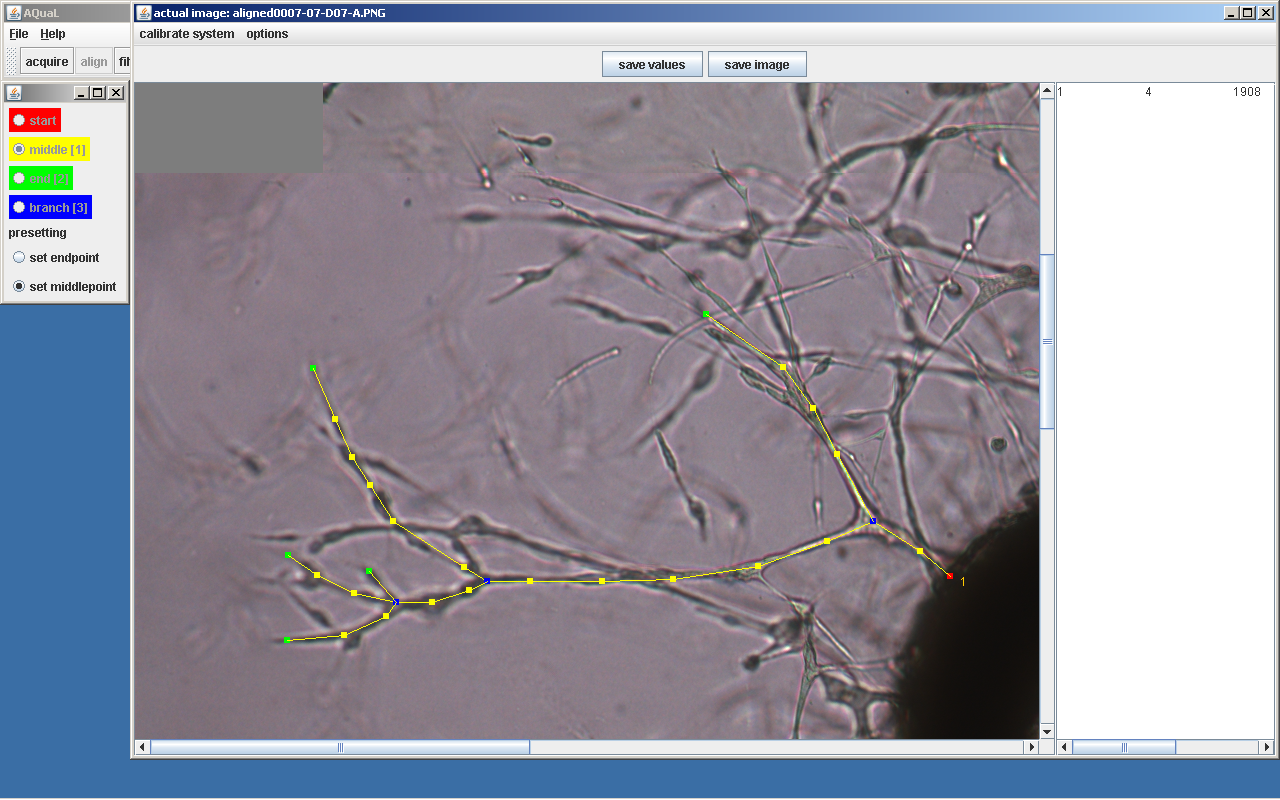
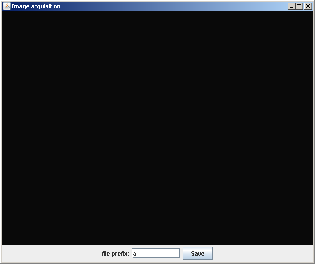
Image acquisition
This program requires the installation of Java Media Framework (JMF) on the computer. JMF is available for free download at the homepage of Sun Microsystems. External hardware through which images are to be acquired needs to be supported by JMF. Upon startup a folder for the acquired images has to be selected.
The live stream of the framegrabber is displayed in the center of the frame. An image is saved by clicking the Save button at the bottom of the frame. Its name consists of the prefix that can be defined in the text field and the number of the acquired image.